I was asked to animate a dot-matrix display for the robotics club recently. They
wanted something that said "Robotics Club" to hang over their door. We had some
old P10(1r) DMDs which I had worked on in the past to make a little scoreboard
for a robot football match. And, even though I am not very good at it, I really
love animating things. So I decided to give it a shot. I ended up writing an
animation software for the DMD in JavaScript which is unfortunately only as
functional as a flipbook. But I had fun animating little person carrying a
balloon, ugly gear trains and a little pixel Wall-E blinking.
Yeah, that's a little Wall-E looking at you. After thinking long and hard about it, I decided that Wall-E is the best robot to look over us all while we do our robotics stuff. Wall-E was also, thanks to his angular design and distinctly recognizable shape, much better suited to a low resolution display than some other things I wanted to do.
Another thing I animated was a little man who carries a balloon and strolls into the DMD where "Robotics Club" is written and just stands there idly for a while, then goes away. I thought it was a cool thing to do, but no one else agreed. So I reluctantly scrapped that idea. I also wanted to animate some other things, like a gear train driven by a hamster, and GIR from Invader Zim (remember that show?). But of course, a monochrome 32x32 matrix doesn't give you much space to play with. I was also limited by time. I'm working almost full time on our minor project, and I also have to attend my classes. For the next version of this screen, I'm planning a much cooler animation, that uses the whole 32x32 screen and the whole 32KB of the AVR program space, and maybe also some form of compression. In this post, I document all the major portions of the project, while also trying to be helpful to people designing DMDs.
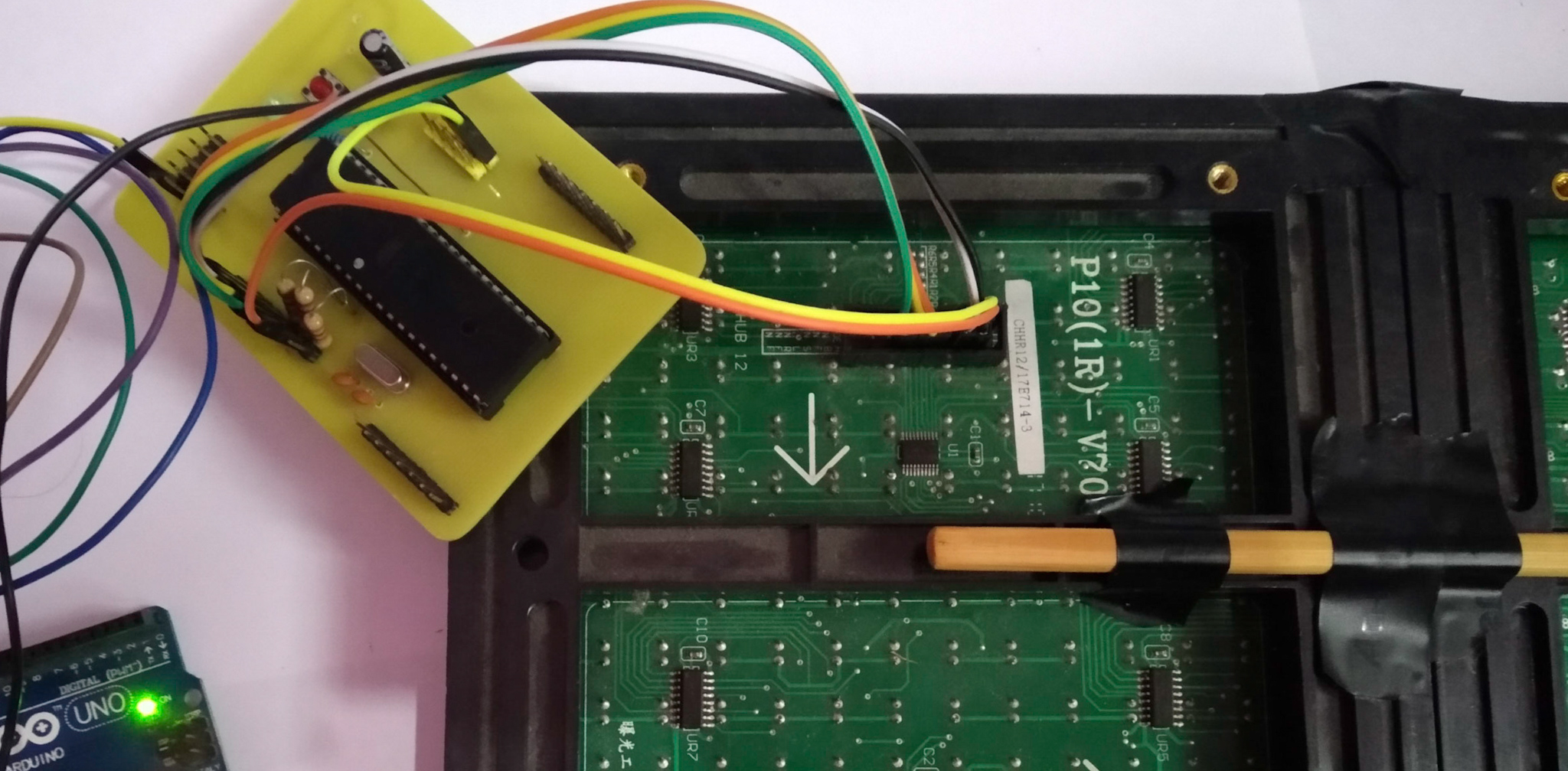
I made all the electronics for the project last semester with Bhuwan. We made the circuit board by hand, doing everything from hack-sawing the PCBs, etching the copper traces with a fumigating solution of FeCl3, drilling the boards and soldering the components. That process, while manual, was very enjoyable. The resulting circuit looks nice and is so robust that from the time it was built, there has never been any hardware bug in the system. I mean, sure, being a MCU based digital circuit doesn't leave much room for bugs. But still, considering the many many many hardware bugs we encountered while doing the robot MIMO (we ended up making 6 iterations for the circuit board), this one was a walk in the park.
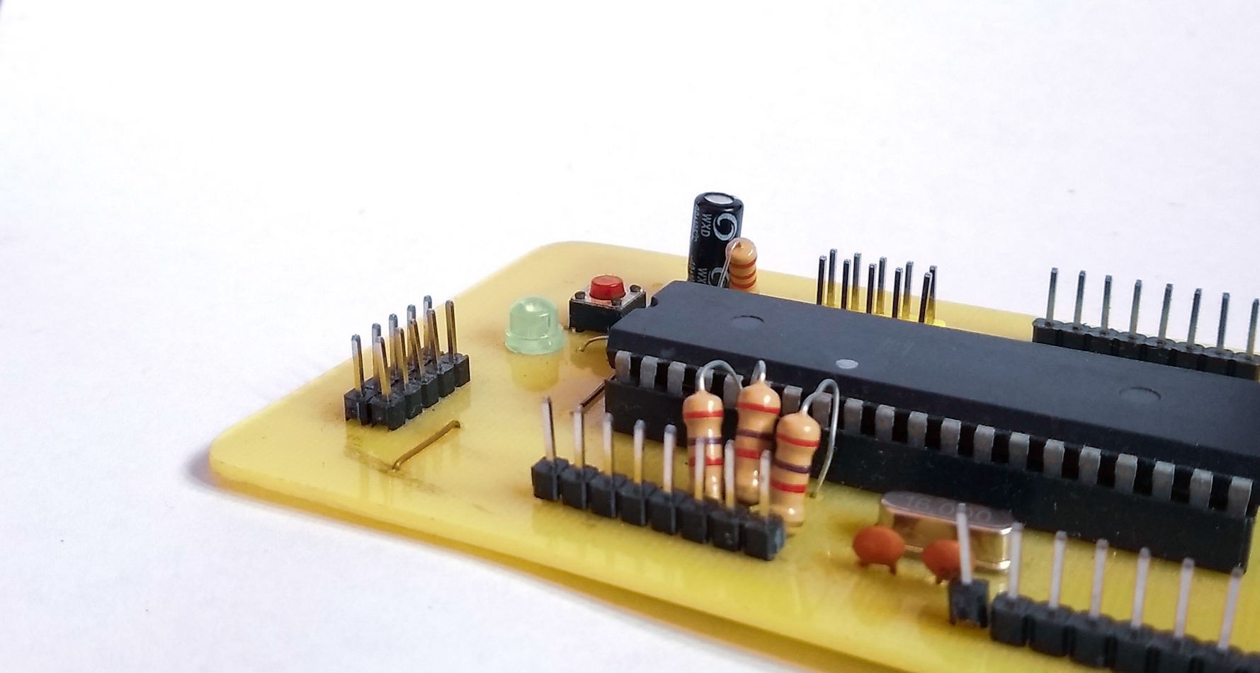
The board is straightforward. It's an Atmega32A with it's support circuitry (oscillators, decoupling capacitors and such) and a bunch of headers: one for connecting the In-System Programmer, one for connecting to a control remote, and one for the Dot-Matrix display.
The display itself (P10(1r)-V70) is a matrix of LEDs all connected to a bunch
of 74HC595 shift registers in series. The DMD takes the following inputs:
- Output Enable (OE)
- Row Selectors (A and B)
- A data line (D)
- A clock line (CLK)
- A Latch line (SCLK)
- A ground
The data line D inputs the data serially, clocked by the CLK line. On the rising edge of the SCLK pin, the data shifted in is displayed on the LEDs. So far, it is exactly as if we were using the 74HC595 directly. But the row selectors complicate things slightly. The people who designed this board have done something really cool. Perhaps to reduce part count, or to keep the board layout simple, or maybe because of fanout issues, they have connected 4 consecutive LEDs to the same set of shift registers. Which rows of the matrix you are addressing depends on the inputs to the selector pins. That is, for A = LOW, B = LOW, the first of the four rows is selected; for A = LOW, B = HIGH, the second; and so on. I will talk more about this further below.
The Animation Software
For various reasons, I had to write the animation software myself. The last time, I had written an animation program on Python using Tkinter. Actually, 'written' is a bad verb to describe that process. I had jerrybuilt the whole system in an hour. And over the course of the next week, I had haphazardly stuck various appendages and functions which made the code very difficult to navigate. On top of that, the program itself was very ugly.
This time, I decided to go with a HTML canvas based approach because I didn't want to download a GUI designer for python, and I sure as heck wasn't going to sit around and waste my precious time learning Tkinter's packs and grids and what not. So anyway, I surprised myself by jerrybuilding the entire system in a few hours, complete with animation frames, onion skinning and the undo feature. The canvas API was so simple, and JavaScript so forgiving, that I didn't even run into any time consuming bug. And the most interesting part? The complete HTML file (with JS and CSS in the same document) is 500 lines of code! It is still bad code, and is very inefficient in many respects. But because it is a means to an end, I allowed myself to take shortcuts. The result is the screenshot below.
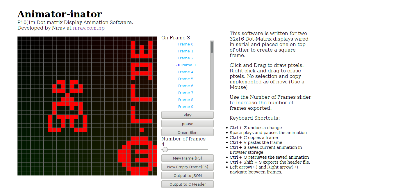
It was so fun to make animations in my own animation program. The only seriously desirable feature that this program lacks is the select and the move feature. The old python version actually had that feature. But I was already pressed for time so I didn't implement it.
The software can be accessed at nirav.com.np/Animator-inator. Feel free to check it out.
The Firmware
I used the same firmware I had written a semester ago. The code itself is straightforward. But I remember it took me a long time to write it, because I didn't have a lot of documentation to consult. So I had to sit there, with the DMD board and it's various pins and wires, and I had to prod this and poke that to figure out how it worked, rather like a puzzle. Thankfully I had worked with the shift registers before, so it took a lot less work than it otherwise would have. This piece of code below is pretty much the only part of the code that counts.
// Slightly altered from original
// for readablity
void clock_selected_lines(char selector) {
  for (int i = 0; i < (WIDTH / 8); i++)
    for (int j = 3; j >= 0; j--)
      clockbyte(display[j * 4 + selector][i]);
  setselector(selector);
  sendpulse(LATCH);
}

int main() {
  init();
  OCR0 = 0xff;
  TIMSK = 2;
  TCCR0 = 0X0b;
  sei();

  int frame = 0;
  while (1) {
    cli();
    disableoutput();
    assign_to_display(frame++);
    enableoutput();
    sei();

    if (frame >= framecount) frame = 0;
    _delay_ms(10);
  }
}
The clock_selected_lines() function takes a value from 0 to 3, and based on
that value, extracts the relevant bits from the display bit matrix to send
into the DMD. Keep in mind that, at one time, only 4 rows (every fourth row) of
the 16 total rows in the DMD can be activated. This is because every group of 4
LEDs, row-wise, is connected to the same pin in the same shift register. Which
of the 4 connected LED lights up is controlled by the 2 selector pins A and B.
To show a complete picture, we have to cycle between the four SEL pins fast
enough that it is below the persistence of vision (10 ms). And each time we
switch rows, we also have to clock in the data in those rows. I know it sounds
complicated, but if you think about it, this little design ingenuity reduced the
part count in the board by a factor of four and minimized the signal propagation
delay inherent in such shift registor based system.
That process is called time-multiplexing, and is used in many kinds of displays throught electronics. The slow mo guys have an amazing video on how displays work. Definitely watch the video, even if you don't see yourself working with displays any time soon. It gives you a new perspective on time.
The main() function simply sets up a timer which calls the
clock_selected_lines() function every certain microseconds and increments the
selector variable by one and makes sure it warps around at 4. Then it enters a
while loop which swaps the display frame every few milliseconds. Keep in mind
that the 10ms value is not the real frame change time. The value increases
somewhat due to being frequently interrupted. I should have set up another timer
for changing frames but I don't think it was necessary for such a simple
program. The sei() and cli() functions turn interrupts on and off. We turn
interrupts off before entering sensitive portion of the code. For example, we
don't want to be interrupted when we copy the next frame from the PROGMEM
(flash) into RAM because we don't want to display half copied frames to the
viewer.
Final thoughts
I enjoyed making this. This DMD gave me a much needed break from the extremely formal and dry world of compiler literature which I have been poring over for weeks in order to make the साक्षर (now मनसा) compiler.
But there is one decision that I regret immensely. In hindsight, it would have been much better if I had written a program to convert any GIF file into a data format suitable for the DMD. It would have been much less glamorous to work on, sure, but it would have given me the free license to work with any pixel based animation software that already exists, and already supports select, move, multi-level undo and all that fancy stuff.
In the next version, I also think it would be awesome if I could implement some form of compression in the animation data. I'm interested in performing some kind of Run-Length Encoding on the delta frames. What I mean is, unless you are animating a moving checkerboard, very little actually changes between a frame and the next. So, if we calculate the delta matrix between every frame and it's successor, we should get a sequence of sparse matrices which we can encode with RLE or some other compression algorithm to achieve good compression on the frames while also being very simple to decompress sequentially. The 2KB RAM on the AVR system should be more than enough.
The whole project is available on my GitHub here